 Korean
 English
Business area
- FMS
- Man Power Service
- Flushing
- Chemical
- Oil
- Water
- Water Jet
- Pressure Test
- Cleaning
- Pig
- Passivasion
- Piping Installaion
- Offshore Plant
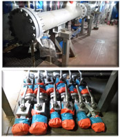
Installation of Piping PROCEDURE
1. Pipework erection
All pipes and fabricated pipe spools shall be inspected before installation and erection to ensure that they are clean and free from any loose contamination. Pipework shall be erected on permanent supports designated for the piping system. Temporary supports shall be kept to an absolute minimum, but to an extent sufficient to protect nozzles and adjacent piping from excessive loads during installation and erection. Pipework shall be fitted in place without springing or forcing to avoid undue stressing of the line or strain being placed on a vessel or item of equipment nozzles, etc. All valves shall be protected against ingress of dirt during any temporary storage.
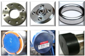
2. Flanged joints and Valves
Before assembly, flanges shall not have any damage that will interfere with the integrity of the joint.
The flanges shall be clean and free from any rust, dirt or other contamination. The joints shall be
brought up flush and square without forcing so that the entire mating surfaces bear uniformly on the
gasket and then mated-up with uniform bolt tension.
Flange protective covers shall be retained on all flange connections on valves and equipment, until
ready for connecting to mating piping. All equipment and pipe components shall be blanked off,
either by pressure test blanks, spades or blinds, to stop any ingress of debris.
● Bolting shall move freely through accompanying bolt-holes at right angle to the flange faces
● There shall be a clear gap between two flange faces before gasket installation. There shall
be sufficient flexibility to install and replace gaskets
● The gap between gasket and flange shall be kept to a minimum
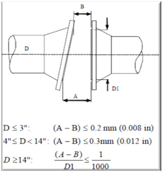
3. Strain Sensitive Equipment with Flange Connections
In addition to the general requirements in this section the following shall apply for flanges
connecting to strain sensitive mechanical equipment e.g. pumps, compressors, turbines, etc.
The flange connection shall be fitted-up in close parallel and lateral alignment prior to tightening the
bolting. Unacceptable forces transferred on to the nozzles shall be prevented.
To achieve this alignment, full advantage shall be taken of the 'cut to fit' allowances and loose
flanges provided. In general, flange connections to strain sensitive equipment shall be the last
connection made on completion of a line or interconnecting system of lines.
With the piping flange fitted and prior to bolting-up the joint, the following tolerances shall be
maintained:
Maximum angular misalignment:

[ Chevron Mafumeira Sul ]
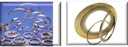
4. Gaskets
All types of gaskets (incl. RTJ) shall be stored and handled in accordance with manufacturer’s instructions. Gaskets, including all types of metal seal rings, shall be replaced after opening or dismantling of any flange connection.
5. Bolting
All flange bolts and stud bolts shall extend fully through their nuts with minimum one thread.
Maximum five thread extension through the nut for bolts less than 1 inch. If tension equipment is
used then there shall be maximum five threads extension through the nut on the opposite side.
All flange bolting and stud bolt threads including the nut/flange contact face shall be fully lubricated
prior to assembly. All flange stud bolts shall be progressively controlled to equalise bolt pressure on
the gasket. There shall be developed a detailed procedure for tensioning/torqueing of flange stud
bolts. Prior to start any tensioning/ torqueing of flange stud bolts written acceptance shall be
obtained.
For Mechanical Joint Hub and Clamp Couplings, tension/torque tables based on manufactures
recommendations shall be established.
Manual torque wrench tools and hydraulic tightening equipment shall be calibrated in accordance
with applicable procedure and have a valid calibration certificate.

6. Pipe support
Piping systems or pipe spools shall not be forced to fit with support locations in such manner that
additional stress is introduced.
Spring support units shall be installed in accordance with the manufacturer’s instructions and pipe
support detail drawing. The spring shall remain in locked position until commissioning/start up.
However, the spring may be temporarily released where necessary to benefit the alignment
operation during installation.
Vent holes in wear plates and trunnions is generally not required. However, when the wear plate or
a trunnion covers a circumferential weld that has not been pressure tested, a vent hole is required
for leak detection.
7. Global tolerances, installation
Hook-up termination points shall be within ±25mm (1 in) in all directions. Overlength may be
provided where required.
Installation tolerances of piping components shall be as required by the individual service of the
piping component including requirements for:
● Maintenance access
● Position relative to surrounding steelwork, equipment, cable tray and HVAC duct routings
● Positioning of pipe supports relative to the structural steel
● Pipe stress